
Not Found
The page or the product you are looking for is no longer available. Please see other products: https://ozrobotics.com/shop/
Browse Hottest Products
-
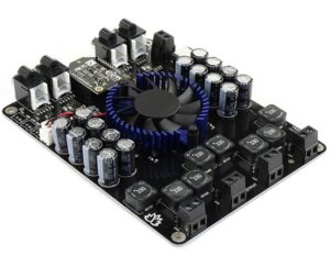
Class D Bluetooth Audio Amplifier Board – 4 x 100W – TSA8498B (Apt-X)
$65.45 Brand: TinySine
-
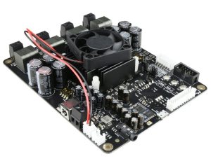
Bluetooth Multipoint with DSP Audio Amplifier Board – TSA8804 V2
$87.50 Brand: TinySine
-

Bluetooth Remote Control Ring with Action Camera Smartphone Controller – Silver
$29.99 Brand: Corebingo
-
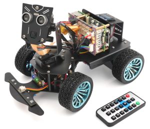
Adeept PiCar-B Metal Smart Robot Car Kit for Raspberry Pi 5/4B/3B+/3B(Raspberry Pi NOT Included)
Sale! Original price was: $149.99.$119.99Current price is: $119.99. Brand: Adeept
-
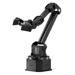
AI Robotic Arm with ESP32 and AT32 Dual-Chip Design – Starter Kit
$293.99 Brand: Hiwonder
-
BLE5.0 Bluetooth Bracelet Beacon supports iBeacon and Eddystone BEC21
Sale! Original price was: $29.99.$26.99Current price is: $26.99. Brand: Oemblue
-
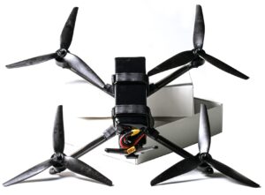
Autonomous Controlled Drone Kit with Day-Vision Intelligent AI and 2.4Ghz 153 KM/H
Sale! Original price was: $1,699.00.$1,599.00Current price is: $1,599.00. Brand: SgUAV Tech
-
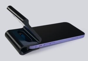
iPhone 3D Scanner – Turn your iPhone or iPad Pro with FaceID into a Full-Color 3D Scanner!
$69.99 Brand: Scanmira
-
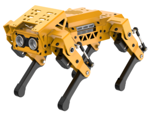
Robot Dog with Open-Source AI and ESP32 Controller – Standard Kit
$349.99 Brand: Hiwonder
-
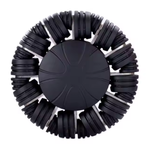
8 Inch (210mm) Heavy Duty TPU Omni-Directional Wheel – 90kg Load Capacity
Sale! Original price was: $129.00.$125.13Current price is: $125.13. Brand: OmniWheelPro
-
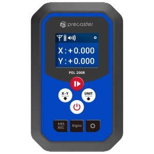
Electronic Level Receiver with High Accuracy – PEL-200
$499.00 Brand: Precaster
-
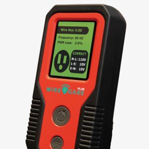
Electric Safety Device
Sale! Original price was: $199.00.$168.00Current price is: $168.00. Brand: Zeroplus Technology
-
Coin Beacon Tag M1 for Tracking Small Assets
Sale! Original price was: $15.00.$10.00Current price is: $10.00. Brand: MOKOSMART
-
LoRaWAN GPS BLE Card Tracker LW010-CT
Sale! Original price was: $50.00.$38.00Current price is: $38.00. Brand: MOKOSMART
-
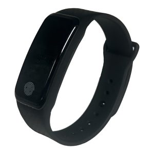
Bluetooth Remote Control Ring with Action Camera Smartphone Controller – Black
$29.99 Brand: Corebingo
-
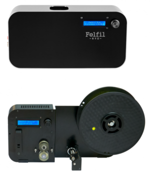
Extrude and Spool Your 3D Printing Filament in a Fast and Easy Way! Bundle Felfil Evo and Spooler
$1,599.00 Brand: Felfil
-
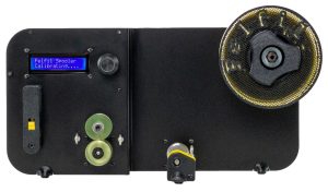
Felfil Spooler Filament Winder for Your Extruder
$859.00 Brand: Felfil
-
3D Printing Filament with Felfil Evo Filament Extruder
$899.00 Brand: Felfil
-
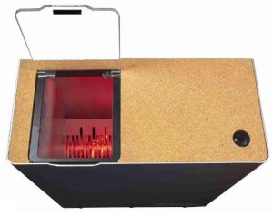
Plastic Shredder – The Most Compact Felfil Plastic Shredder
Price range: $1,499.00 through $1,799.00 Brand: Felfil
-
DALI Bus Power Supply – DALICU-PSU-6-200
$45.00 Brand: SZ Lighting Control