
Not Found
The page or the product you are looking for is no longer available. Please see other products: https://ozrobotics.com/shop/
Browse Hottest Products
-
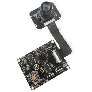
4K-12MP Split USB Camera Module
$154.70 Brand: Dogoozx Technology
-
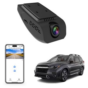
Mangoal Front 4K & Rear Dash Cam with STARVIS Technology,Parking Mode,GPS, App,WiFi and Audio On/Off
Sale! Price range: $100.00 through $399.99 Brand: Mangoal Tech
-
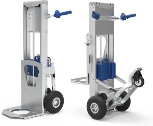
375 lb Electric Material Lift Stacker Motorized Hand Trucks Dolly Moving Cart, Max Lift Height of Loading Plate XSTO LFC170F3
$2,650.00 Brand: XSTO Stair Climbers
-
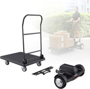
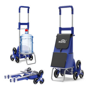
Electric Platform Trucks, Foldable Push Cart Dolly 661 LBS Capacity, 1000W Powered Heavy Duty Flatbed Cart with 360° Swivel Wheels for Warehouse Material Handling ET300P2
$1,599.99 Brand: XSTO Stair Climbers
-
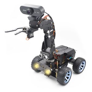
Adeept PiCar Pro V2 AI Powered Robot Kit (Raspberry Pi NOT Included)
Sale! Original price was: $199.99.$164.99Current price is: $164.99. Brand: Adeept
-
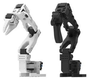
Hiwonder LeRobot SO-ARM101 Open Source 6 Axis Robotic Arm (Advanced Kit/Assembled)
$519.99 Brand: Hiwonder
-
Hiwonder LeRobot SO-ARM101 Open Source 6 Axis Robotic Arm (Standard Kit/Assembled)
$474.99 Brand: Hiwonder
-
Hiwonder LeRobot SO-ARM101 Open Source 6 Axis Robotic Arm (Starter Kit/Assembled)
$440.99 Brand: Hiwonder
-
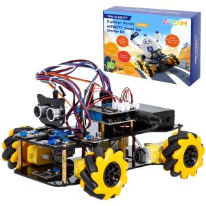
ACEBOTT Smart Robot Car Kit Compatible with Arduino IDE Programming STEM Education Coding Kit
$108.98 Brand: ACEBOTT
-
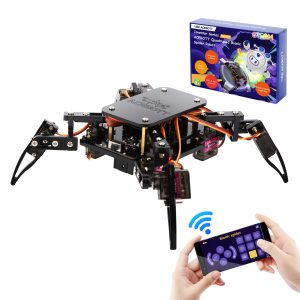
ACEBOTT STEM ESP8266 Arduino Compatible Spider Robot Kit for Robotics Projects
$99.98 Brand: ACEBOTT
-
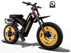
Rundeer Electric Bike Engineered for Adventure and Athletic Performance
Sale! Price range: $2,099.00 through $2,199.00 Brand: RUNDEER
-

Robot Eilik – Touch Interactive Cute Robot with Abundant Emotions – Blue
Sale! Original price was: $149.90.$139.90Current price is: $139.90. Brand: Energize Lab
-

Mini Motorcycle Electric Riding Toy Car Bike with Speaker and LED Lights for Kids – Cruiser 12 Plus
Sale! Original price was: $499.00.$459.00Current price is: $459.00. Brand: Asiwo
-

Robot Eilik – Touch Interactive Cute Robot with Abundant Emotions – Pink
Sale! Original price was: $149.90.$139.90Current price is: $139.90. Brand: Energize Lab
-
Motorized Stair Climbing Shopping Cart – ZW030
$299.99 Brand: XSTO Stair Climbers
-
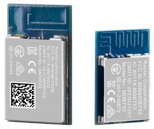
NordicSemi Wi-Fi 6 + Bluetooth LE 5.4 Dual Module-AN02P53P
$10.28 Brand: Raytac Corporation
-
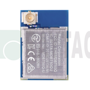
Bluetooth Low Energy BLE Module MDBT50Q-U1MV2
$8.50 Brand: Raytac Corporation
-
4 x 100W Class D Bluetooth Audio Amplifier Board – TSA8498B Apt-X
$65.45 Brand: TinySine