

Unboxing and Assembling a Magni Silver
The Magni comes almost ready to run. Two 12v SLA (Sealed Lead Acid) batteries should be purchased separately. A CR2032 coin cell battery is required for proper operation and must be installed on the back of the main controller board, as shown below.
A 4mm Allen wrench (for M6 screws) is included in the shipping box. In addition, a small Phillips (cross point) screwdriver may be needed for mounting the Raspberry Pi camera.
Opening The Box And Inspecting The Contents
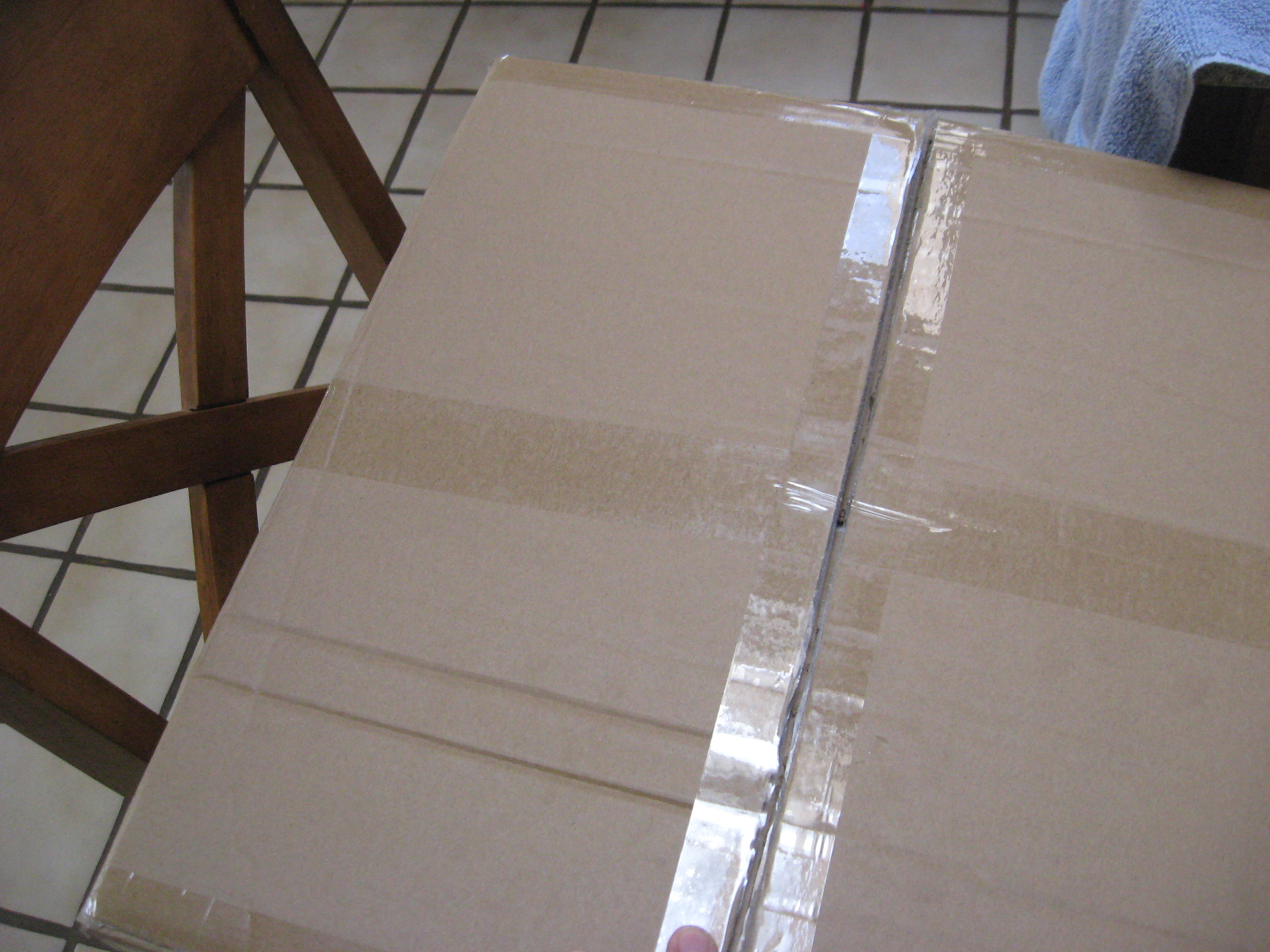
Step 1 – open the box
Inside the box, you will find the battery cables, brackets for the cover plate, fasteners, and a cover plate.
IMPORTANT! DO NOT DAMAGE THE THICK STYROFOAM THAT IS IN THE BOTTOM OF THE CHASSIS; THIS IS LATER USED TO HOLD THE BATTERIES
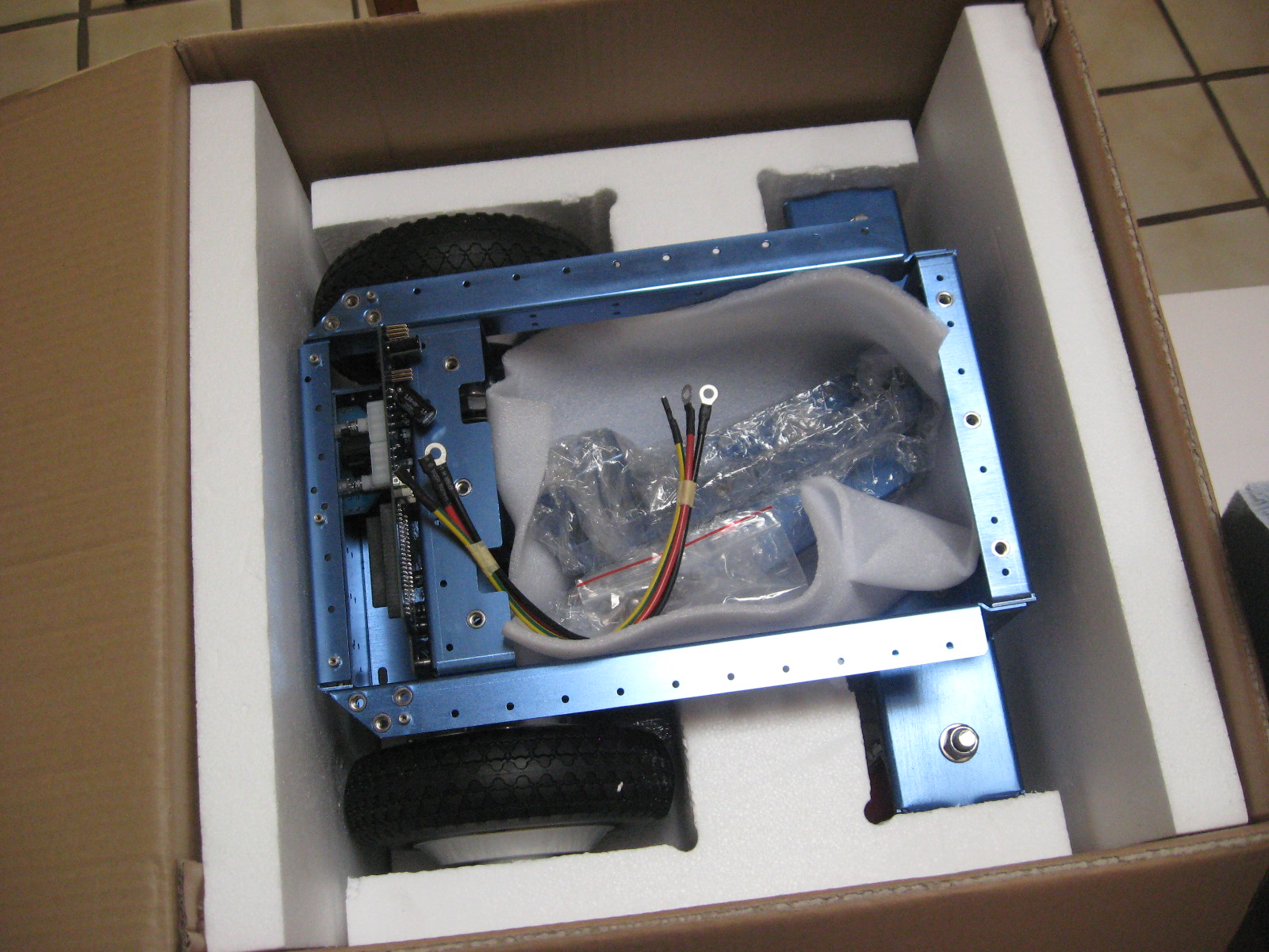
After removing the robot, note the cover plate, which is stored at the bottom of the shipping box.
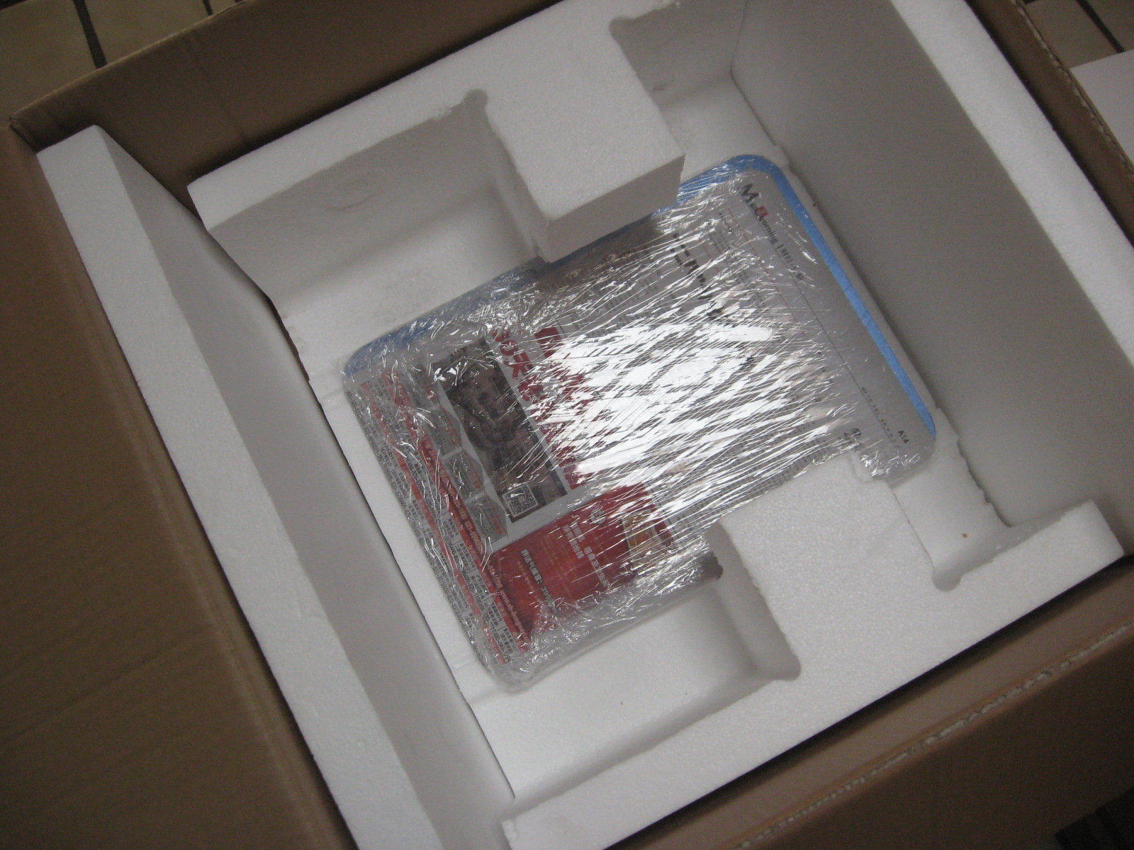
The Raspberry Pi 3 + SD image card can be installed if you have your image with your software (Silver and Gold). However, a default image may already have been installed in the factory.
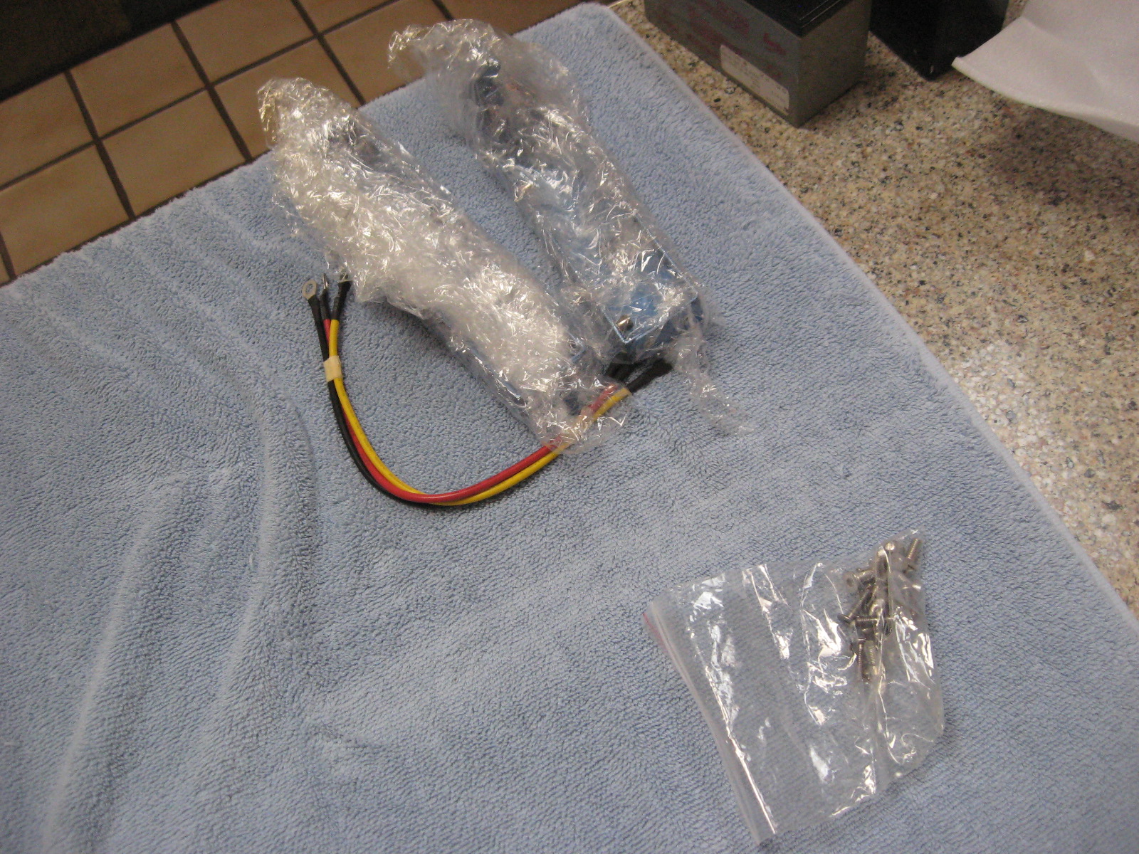
In the small parts bags, you will find fasteners and M4 and M2 Allen wrenches that fit them. The additional sensors (Silver and Gold versions) are wrapped separately.
Bracket Installation
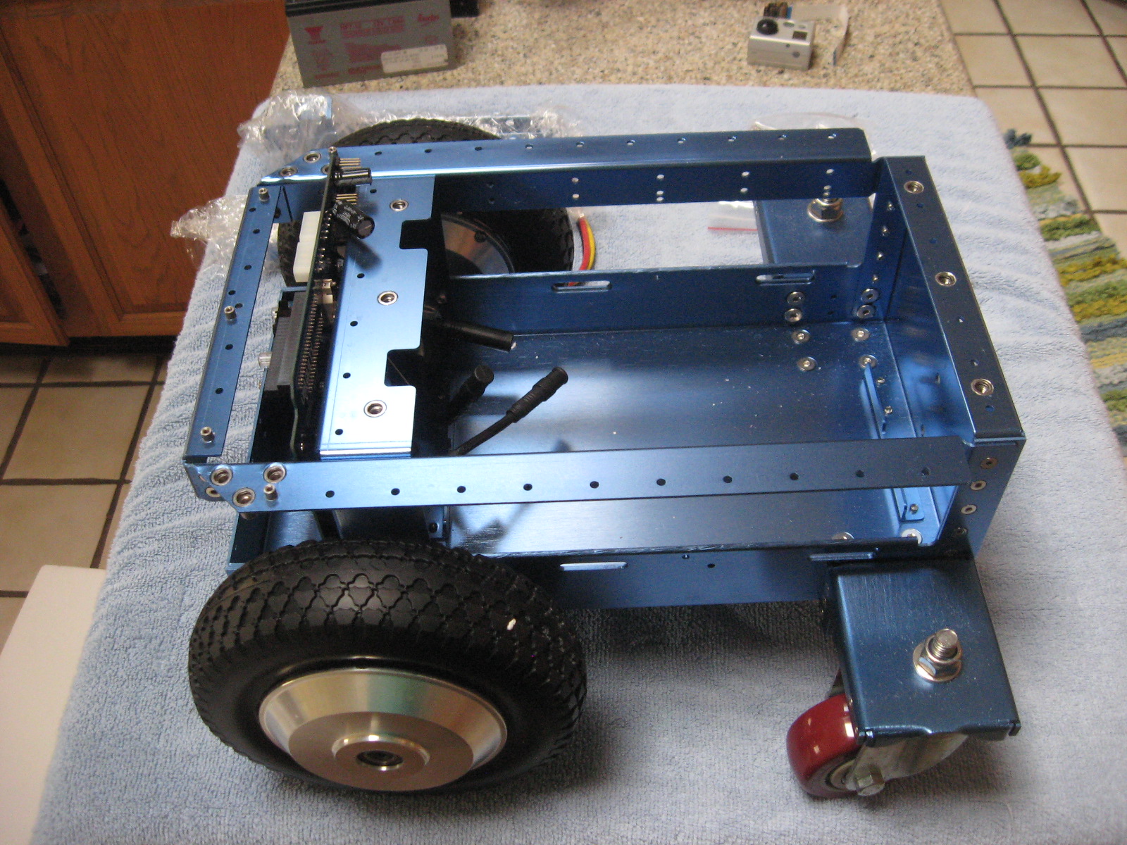
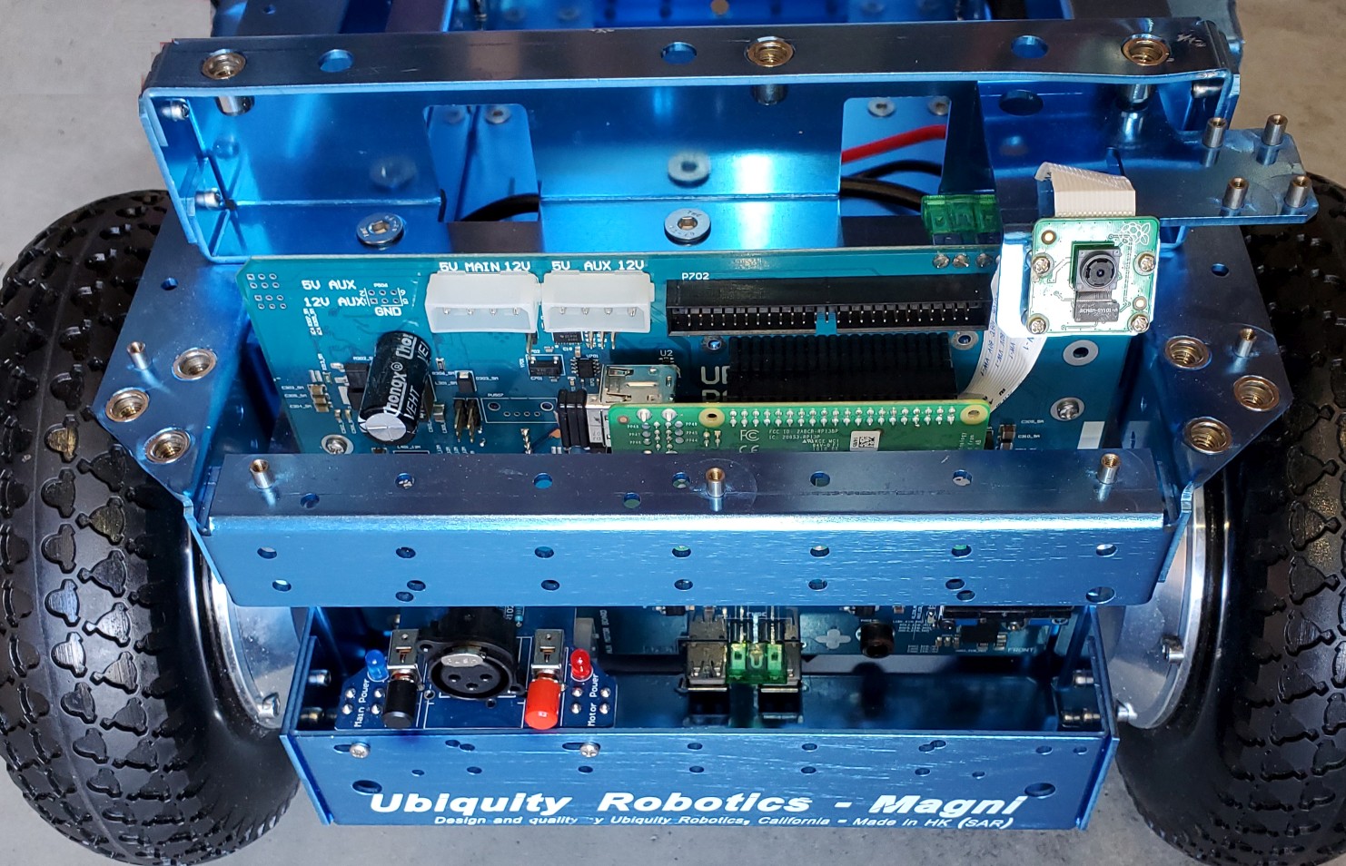
The picture above shows a Magni as shipped without the two brackets. Take time to ensure that the two Motors are connected, which should have been done at the factory. If they are detached, there are arrows on the connectors that (-> <-) show the alignment. These connectors are sometimes hard to insert and separate because it’s hard to grip them. Each motor attaches to the black motor cable from the nearest side of the main PC board to that motor.
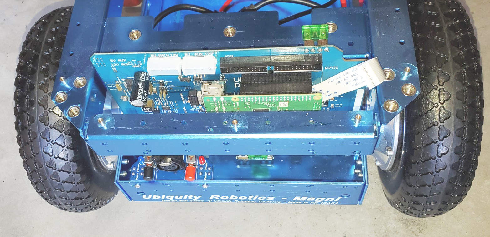
The picture above shows a Magni without the front bracket. In this picture, the Raspberry Pi camera cable is attached to the Raspberry Pi itself, which is part of the setup for the Camera. Decide which camera configuration you will want on your Magni. You should now take a detour to look at THIS_PAGE and decide how to mount the Camera. Once you decide, use the camera setup page and look at the pictures on this page about bracket mounting.
 Front Bracket
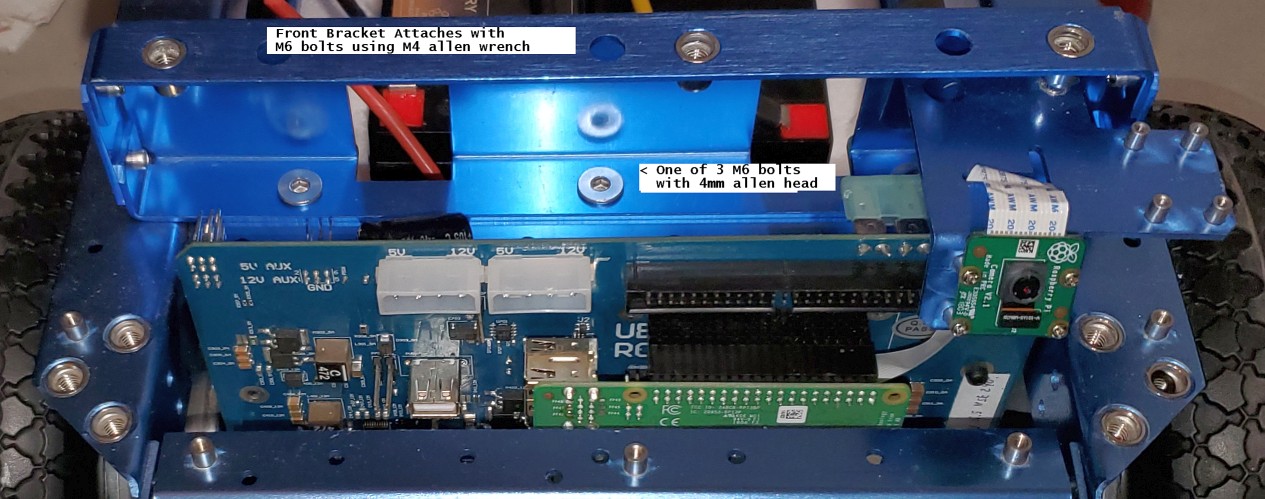
Note that the front and back brackets are different. The front bracket has a shelf for mounting the Raspberry Pi camera. Using 3 of the M6 flat head hex drive screws, attach the bracket. The Allen wrench will go through the top side of the bracket to reach the screw. In this case, the forward-mounted Camera was selected, and the ribbon cable routed to the Camera. Again, see the camera setup page.
 Back Bracket Viewed From Behind
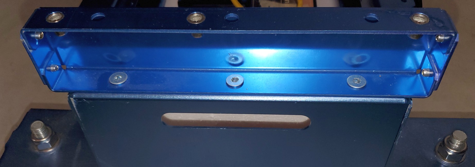
The back bracket attachment also uses 3 M6 flat-head hex drive screws. Here we see the three screws securing the back bracket to the main chassis.
The Mostly Assembled Magni Before Battery Install
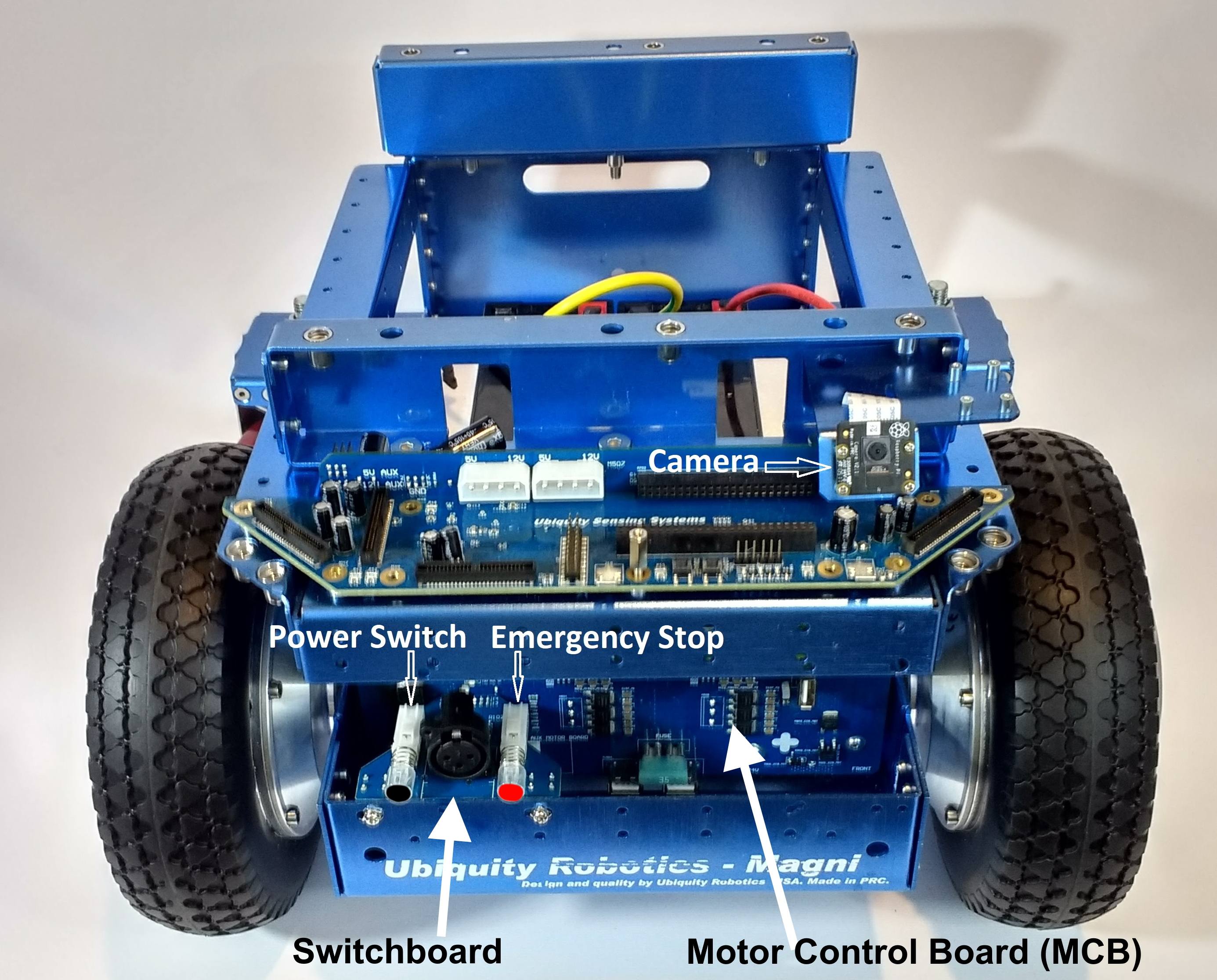
The Front Bracket with the power switchboard and Camera mounted is shown above.
The Main Power switch is the black switch to the left above the first “U” in Ubiquity. On recent Switchboards, it will say ‘Main Power’ next to the blue LED.
The Motor Power is the red switch for the power to the wheels above the “y” of Ubiquity printed on the chassis. On recent Switchboards, it will say ‘Motor Power’ next to the red LED.
For both power switches, the ‘ON’ position is when the switch is out, and when pushed in, the switch will be ‘off.’
The charging port is between the two switches.
The next step will be to install the batteries. At this time, push both of the switches IN, which will turn all power off as you connect the batteries.
Main Power Battery And Wheel Cables Installation
First, a picture of a fully assembled Magni using 2 of the seven amp-hour batteries and having the motor cables attached for both wheels.
Use the thick styrofoam cutout piece that came with your Magni in the chassis bed. It holds the most common battery types in place even if the robot bumps things or is moved around.
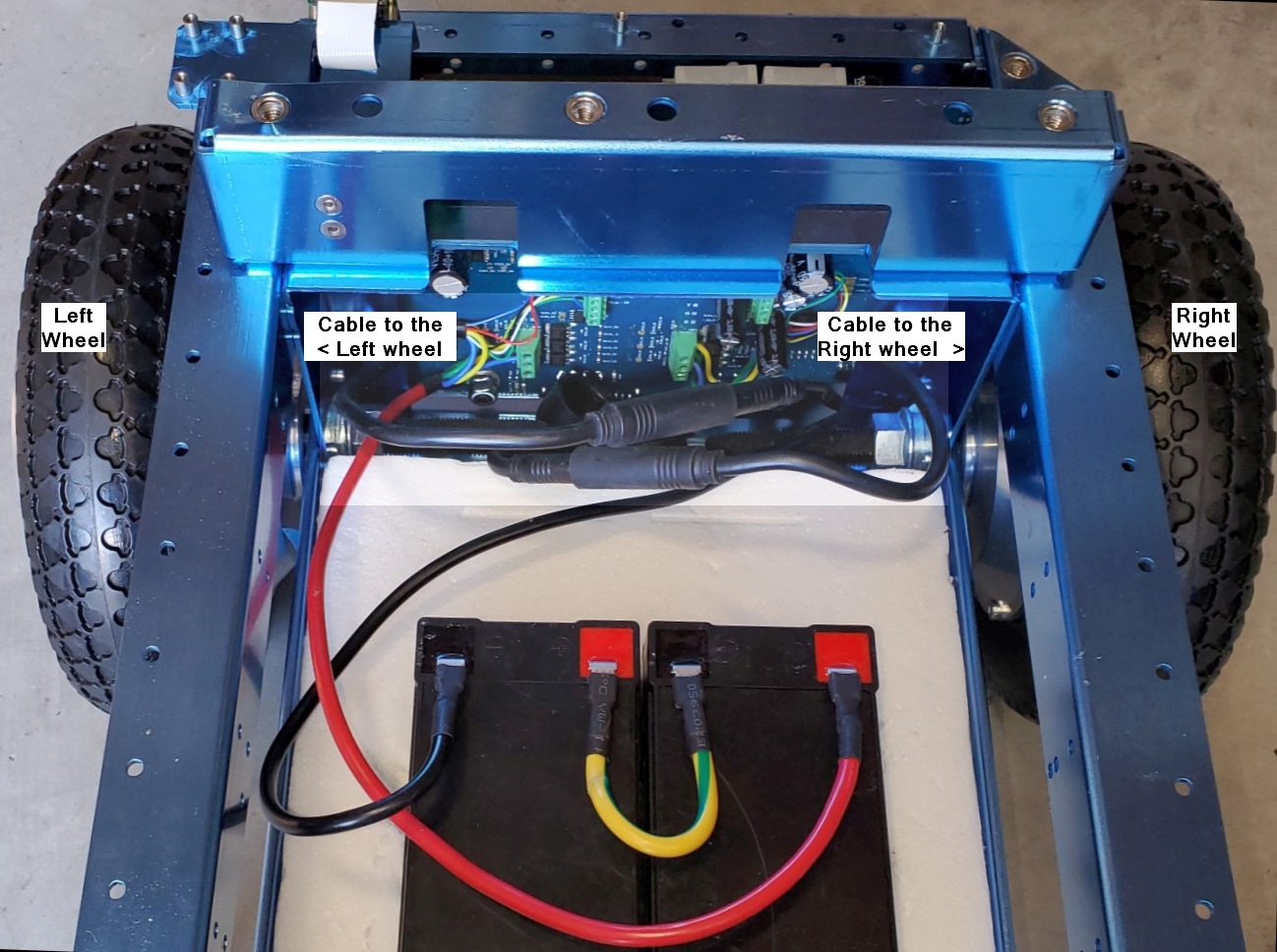
The picture above shows proper cable connections for the batteries and wheels.
The wheels should be properly connected from the factory. As seen in this picture, notice that the cable attached to the two green terminal strips on the right of the back of the main MCB board goes to the right wheel. The cable that comes from the two green terminal strips seen on the left of the back of the MCB board goes to the left wheel.
Battery Power cable Connectors
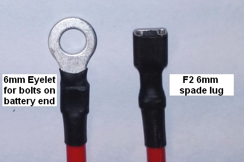
The regular MCB power cables attached at the factory are set up to connect to SLA (Sealed Lead Acid) batteries using an F2 (6mm – 1/4 inch) male spade or flat connectors. Some smaller batteries may use the F1 (3/16 inch) male flat connector, and the cables we typically attach will work on those as well. We also include alternate power cables with 6mm loop connections for larger high-capacity batteries with bolts. Below is a picture of both connectors that a battery may require.
Battery to MCB Power Cable details
For the main power cables, the red power cable goes to the positive of the battery on the right. The yellow cable connects the positive of the left battery to the negative of the battery shown on the right. The black cable goes from the negative terminal of the battery on the left to the ground on the robot.
There are cables for both spade-type and screw-type battery terminals. A 24-volt battery charger is included in the package (Photo not available). The recommended batteries are of the type specified by UB12xxx, where xxx specifies Amp Hours. Commonly UB1250, UB1290, or UB12150 are used. Since it is unknown what size and shape the batteries will be, it is the user’s responsibility to see they are secured in the chassis using straps or packing material.
The Motor cables to the Wheels
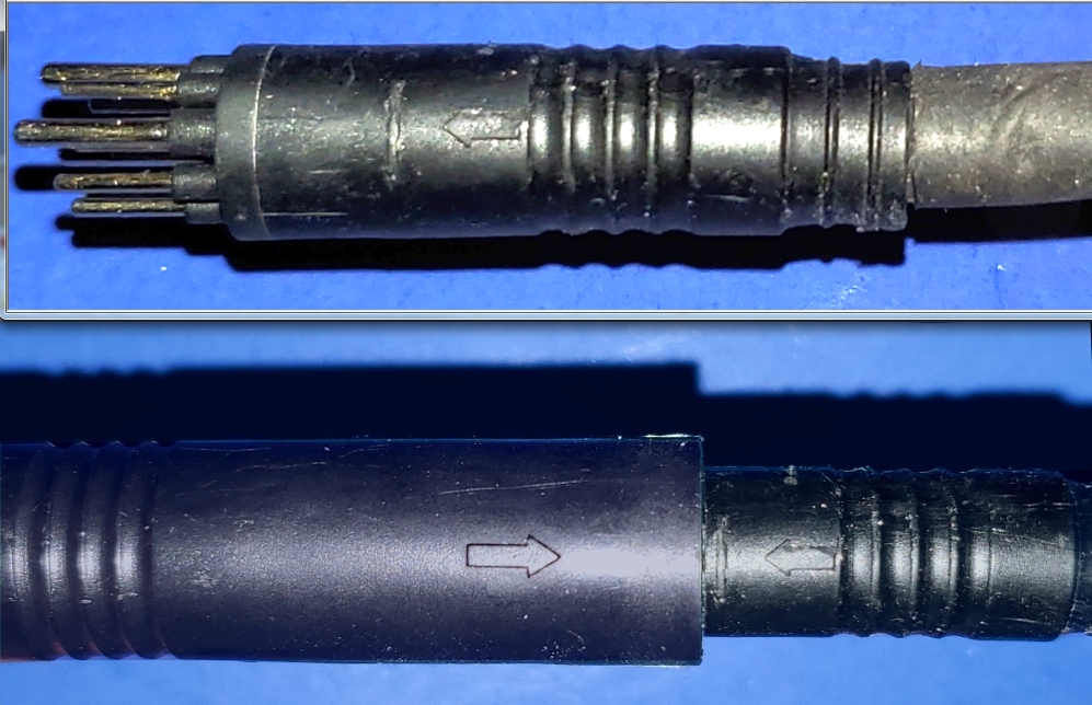
The wheels require a high-current cable that also holds the wheel encoder wires. This cable can be very difficult to detect and only slightly easier to install because it has a very tight fit. Below is a picture of the male pin end, and below that is a properly connected motor cable.
Take note of the small arrows, which can be hard to see, but mark the critical location, and the cables will only fit together if the two sides align the arrow markings.
The Real-Time Clock Battery
Make sure to install the CR2032 real-time clock battery.
Flat Top Plate Install
The top plate should be the last thing attached, using 6 M6 machine screws. Notice that there is one 10mm or so hole in one corner of the plate that is meant to allow the Camera, if in an ‘upward’ position, to see the ceiling, so be aware of that as you put the top plate on the robot.
Note that the countersunk holes should be on the top.
Power Switches
Now you can turn your robot on by pressing the ON switch (the one colored BLACK) and following the guide on connecting to it.
Revision c91e495c.
Copyright (c) 2022, Ubiquity Robotics. BSD 3-Clause License