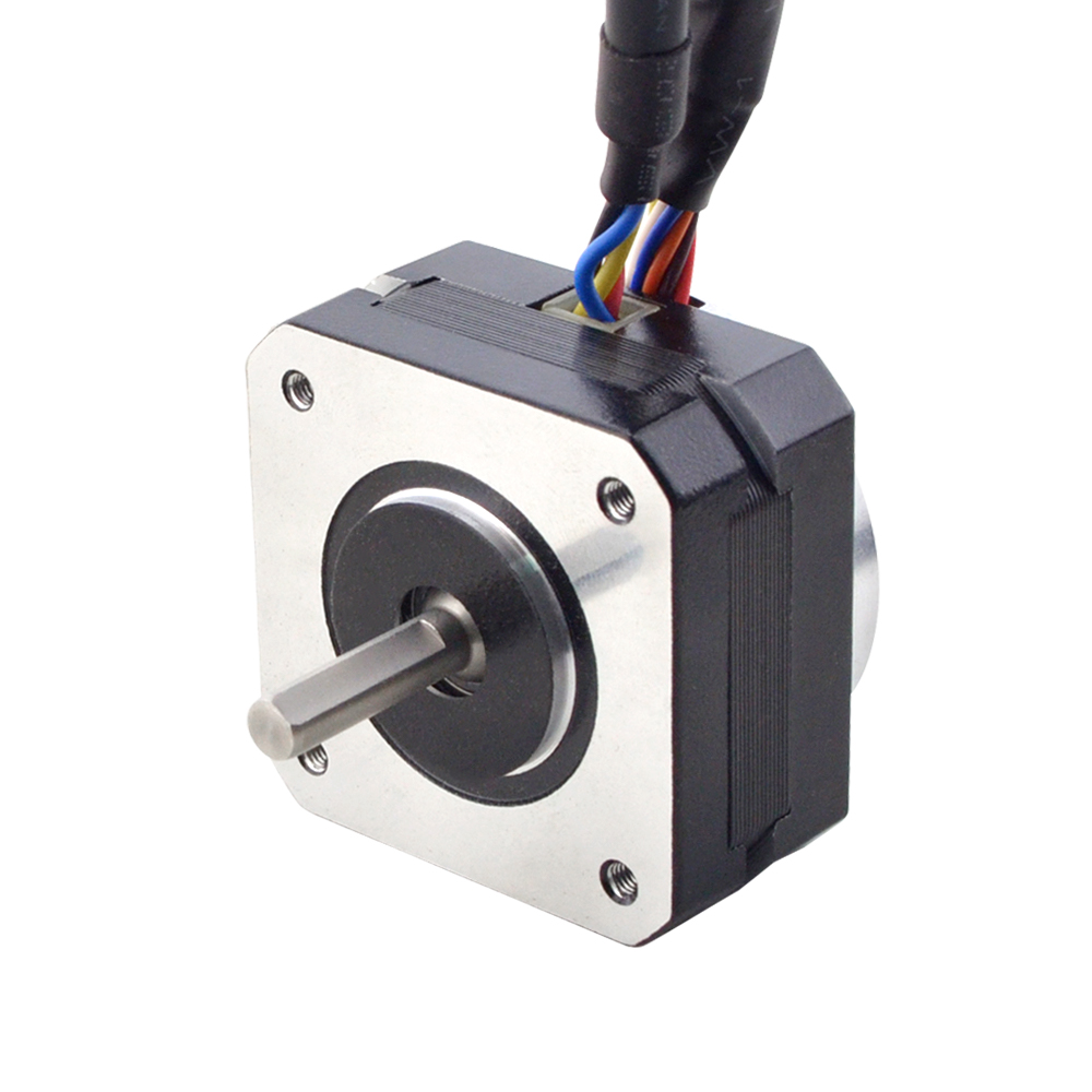
Under different voltages, the performance of stepper motors will be different. Generally, the higher the voltage, the better the speed and torque performance of the stepper motor. However, increasing the voltage also causes an increase in current, which may overheat the motor and possibly even damage the driver.
The motor’s low-speed vibration will be larger when working under high voltage. We recommend that the driving voltage be selected according to the size of the motor base (but may be limited by the driver).
Motor
Voltage
NEMA8—17
12-24VDC
NEMA23—24
24-48VDC
NEMA34
36-60VDC
NEMA42
60-100VDC
To properly drive a stepper motor at different voltages, the following points need to be considered:
Current: The stepper motor has a rated current, the best working current considered in the design. If the current exceeds the rated value, the electric
The machine may overheat and be damaged. At different voltages, the current may vary. To protect the motor, a current limit can be used
driver to control the current.
Driver: An appropriate driver must be used to drive the stepper motor at different voltages properly. The driver should be able to input
The voltage adjusts the output current to maintain a constant current. This can be achieved using a constant current source driver, which automatically adjusts the
output voltage to maintain a constant current.
In summary, stepper motors work at different voltages as follows: A change in voltage causes a change in current, so you need to use an appropriate driver to protect the motor and achieve optimum performance. When designing the system, the rated voltage and current of the motor should be considered, an appropriate driver should be selected, and control strategies should be used. Source
A Technology Marketplace is a physical or online platform that sells specific types of goods from verified sellers, such as hardware and software, to consumers, businesses, and schools.
Oz Robotics is a Technology Marketplace where you can find Robotics, Drones, 3D Printers, Electronic Kits, Arduino, Raspberry PI, Motors, IoT, Actuators, Mecanum and Omni Wheels, Cameras, Sensors, Virtual Reality, STEM, and Mobile Gadgets from verified manufacturers by Oz Robotics for quality and affordable pricing.
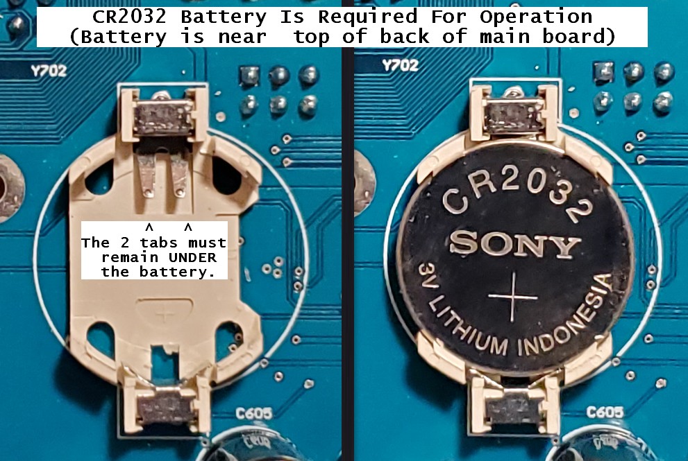
The Magni comes almost ready to run. Two 12v SLA (Sealed Lead Acid) batteries should be purchased separately. A CR2032 coin cell battery is required for proper operation and must be installed on the back of the main controller board, as shown below.
A 4mm Allen wrench (for M6 screws) is included in the shipping box. In addition, a small Phillips (cross point) screwdriver may be needed for mounting the Raspberry Pi camera.
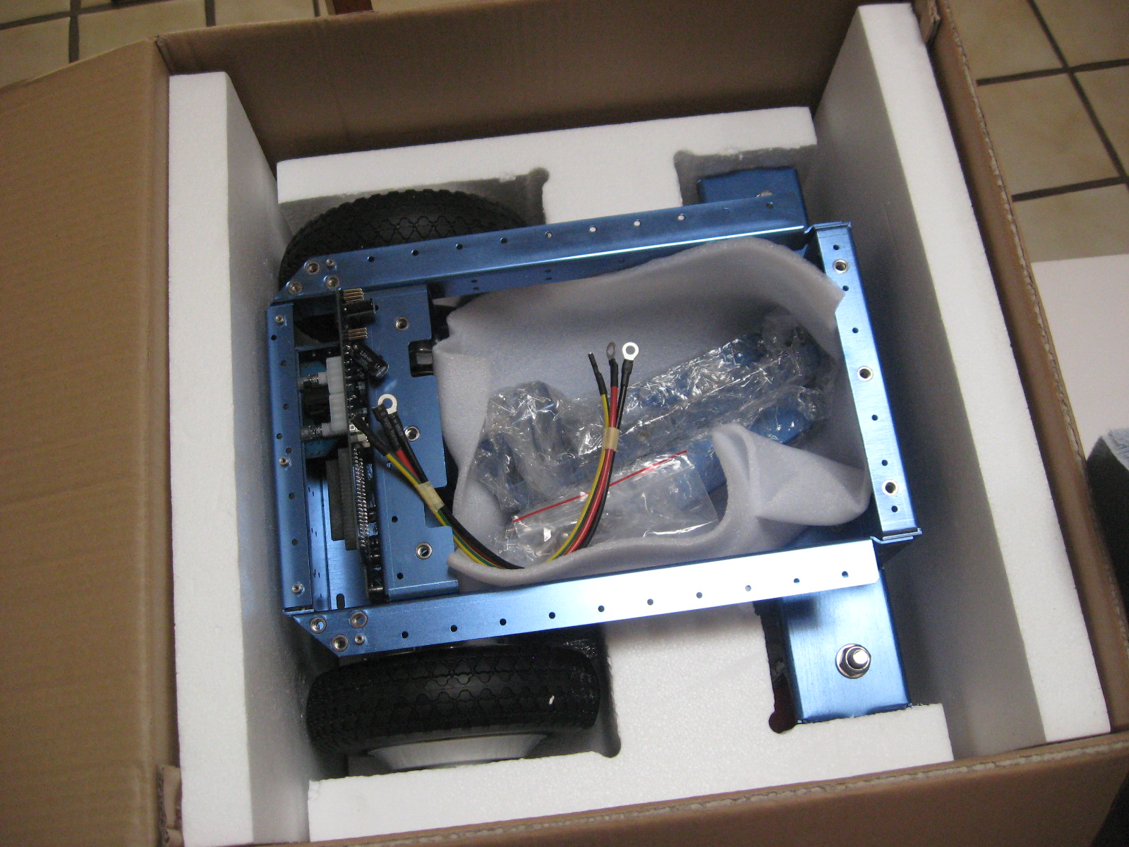
Opening The Box And Inspecting The Contents
Step 1 – open the box
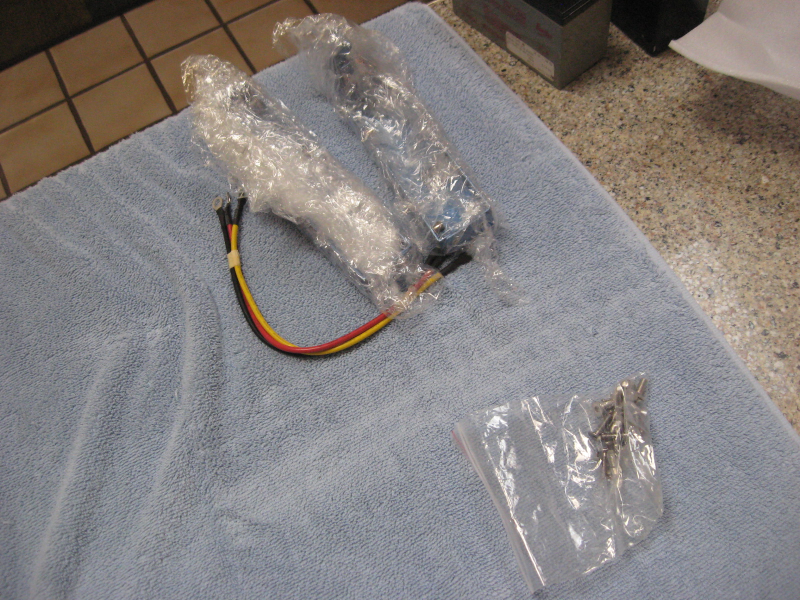
Inside the box, you will find the battery cables, brackets for the cover plate, fasteners, and a cover plate.
IMPORTANT! DO NOT DAMAGE THE THICK STYROFOAM THAT IS IN THE BOTTOM OF THE CHASSIS; THIS IS LATER USED TO HOLD THE BATTERIES
After removing the robot, note the cover plate, which is stored at the bottom of the shipping box.
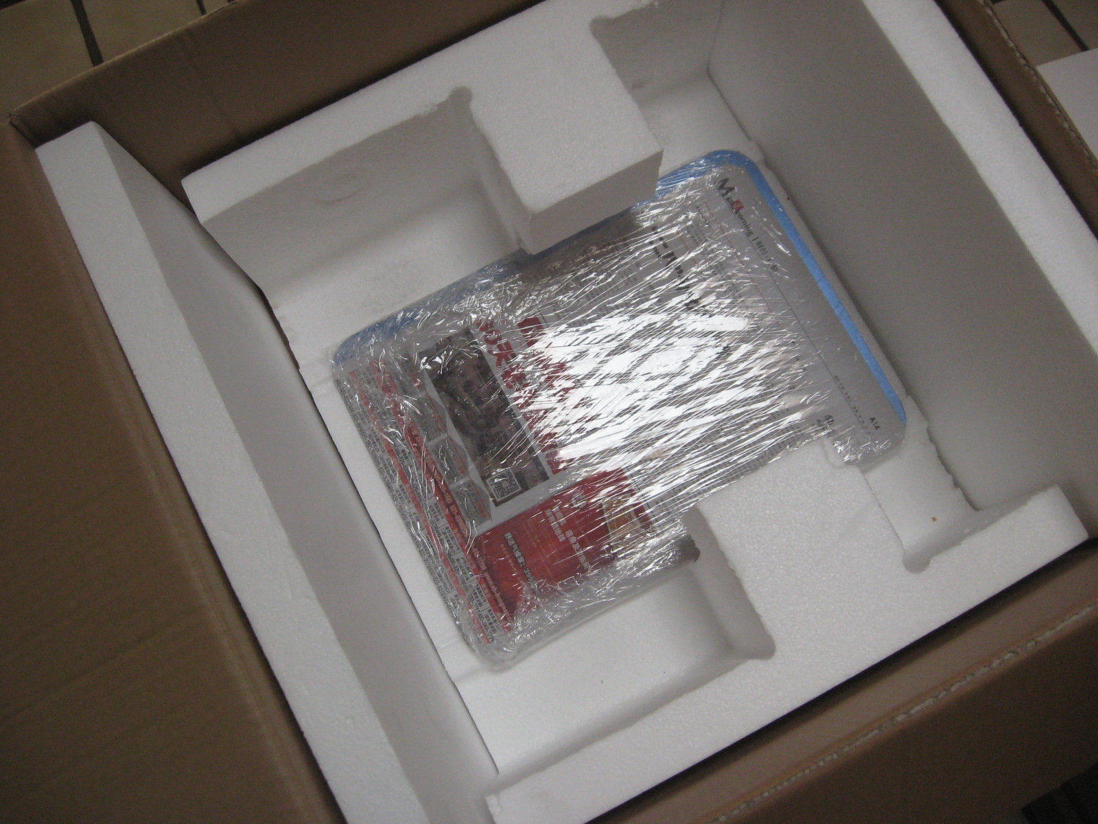
The Raspberry Pi 3 + SD image card can be installed if you have your image with your software (Silver and Gold). However, a default image may already have been installed in the factory.
In the small parts bags, you will find fasteners and M4 and M2 Allen wrenches that fit them. The additional sensors (Silver and Gold versions) are wrapped separately.
Bracket Installation
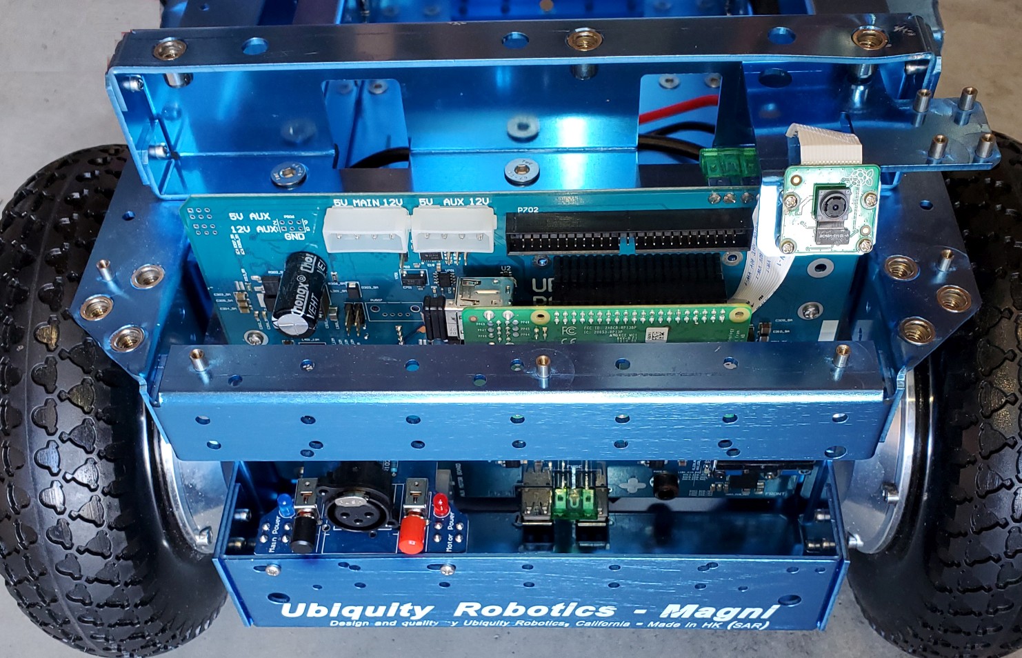
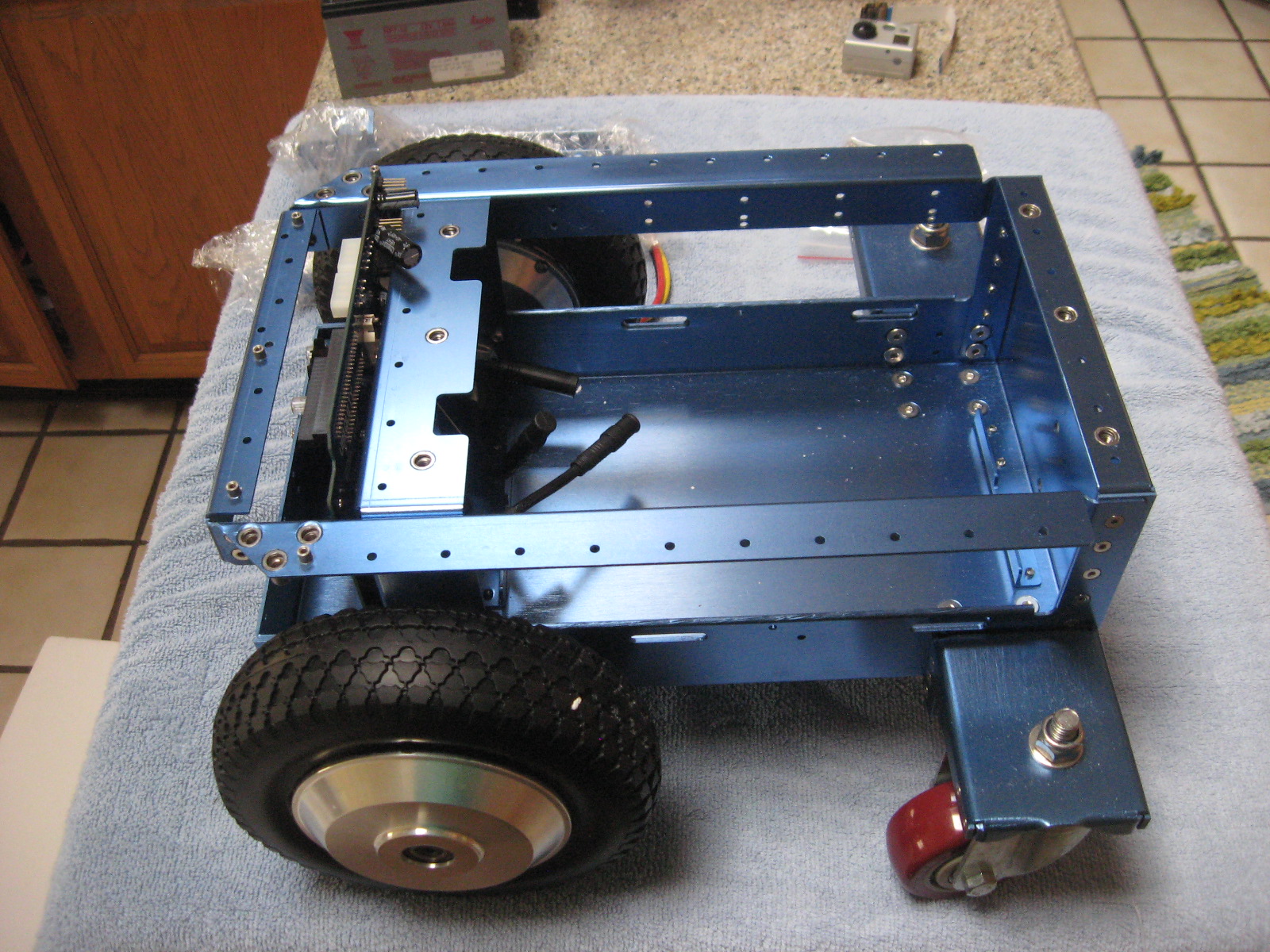
The picture above shows a Magni as shipped without the two brackets. Take time to ensure that the two Motors are connected, which should have been done at the factory. If they are detached, there are arrows on the connectors that (-> <-) show the alignment. These connectors are sometimes hard to insert and separate because it’s hard to grip them. Each motor attaches to the black motor cable from the nearest side of the main PC board to that motor.
The picture above shows a Magni without the front bracket. In this picture, the Raspberry Pi camera cable is attached to the Raspberry Pi itself, which is part of the setup for the Camera. Decide which camera configuration you will want on your Magni. You should now take a detour to look at THIS_PAGE and decide how to mount the Camera. Once you decide, use the camera setup page and look at the pictures on this page about bracket mounting.
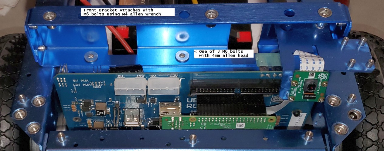
Front Bracket
Note that the front and back brackets are different. The front bracket has a shelf for mounting the Raspberry Pi camera. Using 3 of the M6 flat head hex drive screws, attach the bracket. The Allen wrench will go through the top side of the bracket to reach the screw. In this case, the forward-mounted Camera was selected, and the ribbon cable routed to the Camera. Again, see the camera setup page.
Back Bracket Viewed From Behind
The back bracket attachment also uses 3 M6 flat-head hex drive screws. Here we see the three screws securing the back bracket to the main chassis.
The Mostly Assembled Magni Before Battery Install
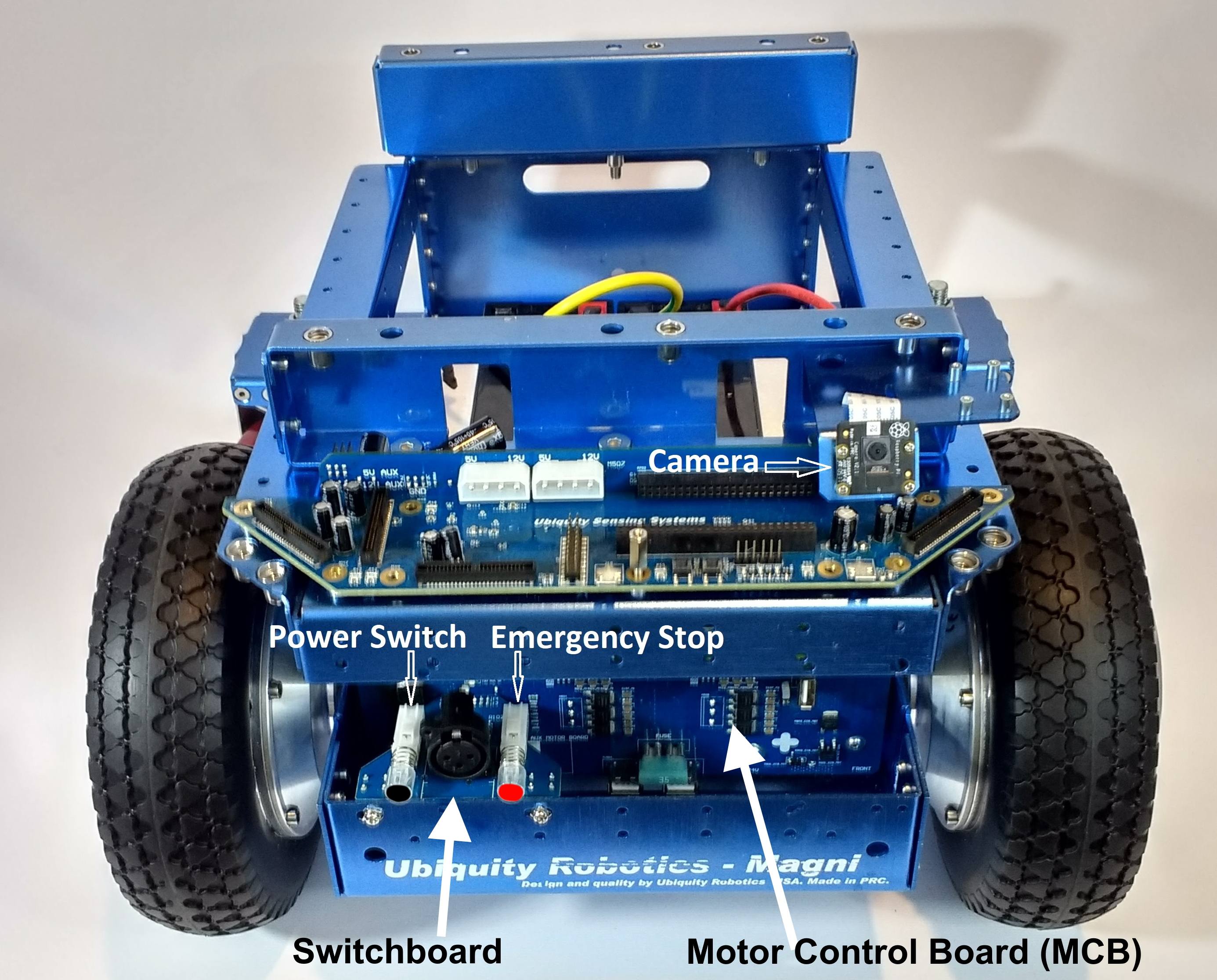
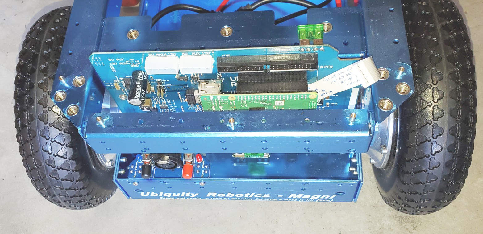
The Front Bracket with the power switchboard and Camera mounted is shown above.
The Main Power switch is the black switch to the left above the first “U” in Ubiquity. On recent Switchboards, it will say ‘Main Power’ next to the blue LED.
The Motor Power is the red switch for the power to the wheels above the “y” of Ubiquity printed on the chassis. On recent Switchboards, it will say ‘Motor Power’ next to the red LED.
For both power switches, the ‘ON’ position is when the switch is out, and when pushed in, the switch will be ‘off.’
The charging port is between the two switches.
The next step will be to install the batteries. At this time, push both of the switches IN, which will turn all power off as you connect the batteries.
Main Power Battery And Wheel Cables Installation
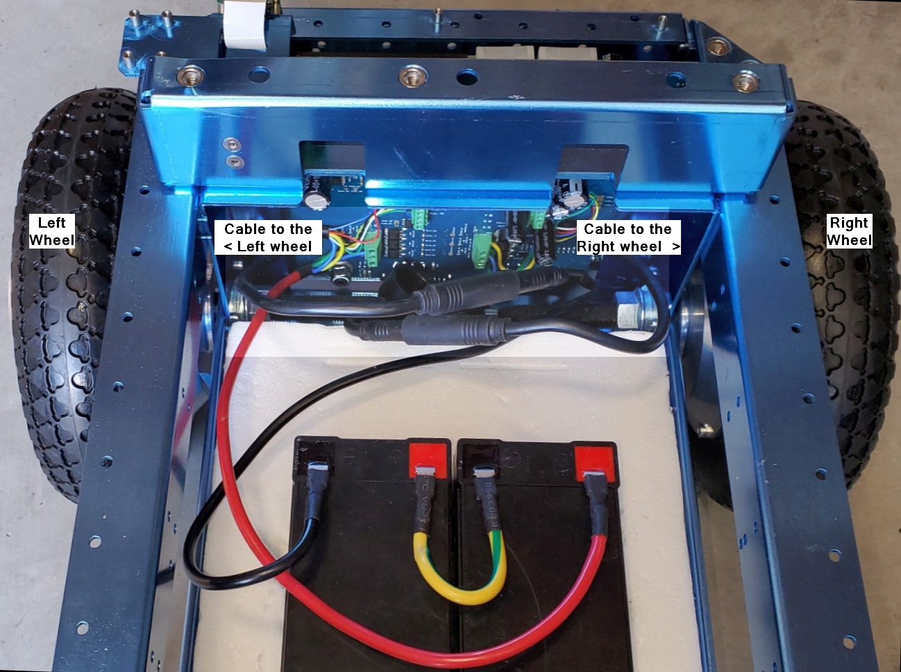
First, a picture of a fully assembled Magni using 2 of the seven amp-hour batteries and having the motor cables attached for both wheels.
Use the thick styrofoam cutout piece that came with your Magni in the chassis bed. It holds the most common battery types in place even if the robot bumps things or is moved around.
The picture above shows proper cable connections for the batteries and wheels.
The wheels should be properly connected from the factory. As seen in this picture, notice that the cable attached to the two green terminal strips on the right of the back of the main MCB board goes to the right wheel. The cable that comes from the two green terminal strips seen on the left of the back of the MCB board goes to the left wheel.
Battery Power cable Connectors
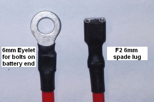
The regular MCB power cables attached at the factory are set up to connect to SLA (Sealed Lead Acid) batteries using an F2 (6mm – 1/4 inch) male spade or flat connectors. Some smaller batteries may use the F1 (3/16 inch) male flat connector, and the cables we typically attach will work on those as well. We also include alternate power cables with 6mm loop connections for larger high-capacity batteries with bolts. Below is a picture of both connectors that a battery may require.
Battery to MCB Power Cable details
For the main power cables, the red power cable goes to the positive of the battery on the right. The yellow cable connects the positive of the left battery to the negative of the battery shown on the right. The black cable goes from the negative terminal of the battery on the left to the ground on the robot.
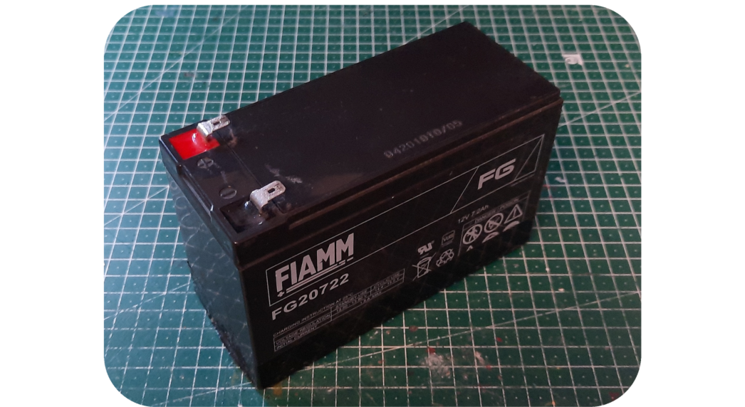
There are cables for both spade-type and screw-type battery terminals. A 24-volt battery charger is included in the package (Photo not available). The recommended batteries are of the type specified by UB12xxx, where xxx specifies Amp Hours. Commonly UB1250, UB1290, or UB12150 are used. Since it is unknown what size and shape the batteries will be, it is the user’s responsibility to see they are secured in the chassis using straps or packing material.
The Motor cables to the Wheels
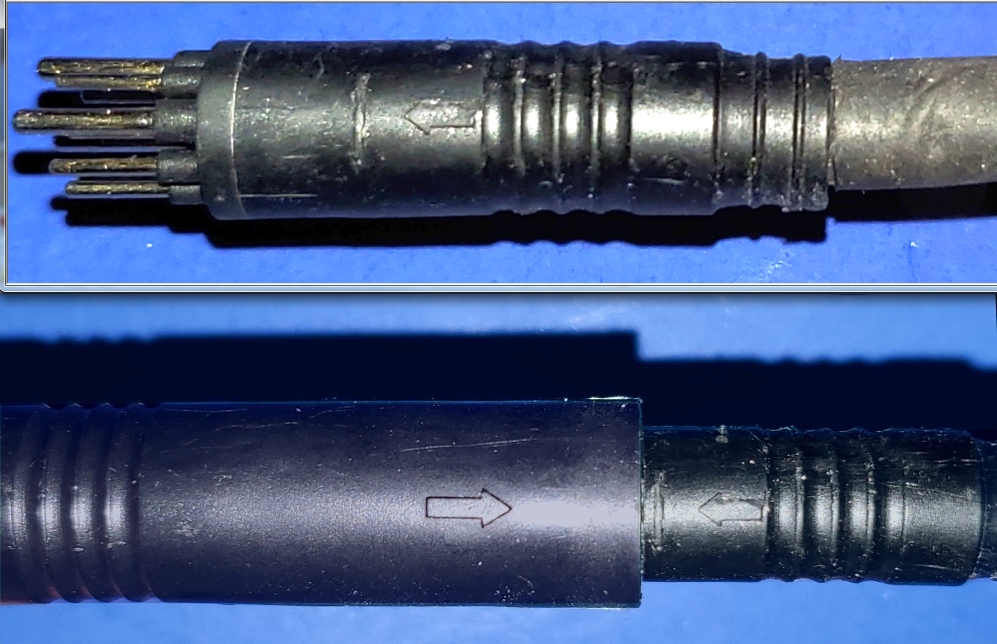
The wheels require a high-current cable that also holds the wheel encoder wires. This cable can be very difficult to detect and only slightly easier to install because it has a very tight fit. Below is a picture of the male pin end, and below that is a properly connected motor cable.
Take note of the small arrows, which can be hard to see, but mark the critical location, and the cables will only fit together if the two sides align the arrow markings.
The top plate should be the last thing attached, using 6 M6 machine screws. Notice that there is one 10mm or so hole in one corner of the plate that is meant to allow the Camera, if in an ‘upward’ position, to see the ceiling, so be aware of that as you put the top plate on the robot.
Note that the countersunk holes should be on the top.
Power Switches
Now you can turn your robot on by pressing the ON switch (the one colored BLACK) and following the guide on connecting to it.
The robot ships by air worldwide. The batteries are not included to keep shipping costs down, as they are difficult to ship worldwide, and safety restrictions vary by destination. The recommended lead acid batteries are easy to source locally.
An added advantage of not including batteries is that the robot accepts different battery sizes, so the user can select batteries depending on whether they prefer a long-endurance heavier robot or a short-endurance lighter robot. In short, you need to find your batteries to put in the robot, and these are commonly available online or in local stores that supply products for scooters, wheelchairs, uninterrupted power supply systems, or even automotive.
VOLTAGE CONNECTED TO THE MAIN CONTROL BOARD (MCB) MUST REMAIN 30.0V OR LESS AT ALL TIMES!
Specific Qualified Lead Acid Batteries
The robot requires two 12V lead acid-style batteries wired up in series to provide 24 volts, and typically, we recommend one of the choices in this section.
Battery Size
Capacity (Ah)
Runtime (hours)
Notes
1250/1255
4 – 6
3 – 4
They are used when the portability of the robot is at a premium – for example if you are traveling by air with the robot.
1270
7 – 10
6 – 8
This size battery makes the robot still light enough to lift.
12350
30 – 35
12 – 24
It is recommended only for those who must have extraordinary endurance. This sized battery makes the robot sufficiently heavy that it will be difficult for most users to lift.
A typical 1270 7.2Ah 12V battery, two of these are most commonly used with the Magni.
The stock battery charger we supply is ONLY FOR LEAD ACID batteries and will NOT work and may be dangerous for other battery technologies.
While any set of batteries that can together supply roughly 24V will work, the ideal battery type is a deep-cycle lead acid battery. Typically, for the smaller batteries (1250, 1255, 1270), a gel-type lead acid is common, and for the larger types (12350), an AGM type is more common. Li battery types will work, but it should be a drop-in replacement type fully compatible with a lead acid charging cycle and have its battery balancing system (typically LiFePO4). As the system is designed for lead acid batteries if you use anything else, the battery state topic could give misleading numbers as to the true battery state, but this will not affect the ability of the robot to drive properly.
Compartment Size
We ship Magni with a foam cut-out that nicely holds two 1270 format Lead Acid batteries. Do not discard the foam inserts along with the packaging.
The floor of the battery compartment is always at least 205mm x 258mm. Due to manufacturing tolerances, it may be larger, but that cannot be guaranteed.
From the floor to the top of the top rails on the side, we have 135mm of height. Batteries can go up taller to the top flat metal plate, and that would be a height of 184mm. These measurements are intentionally meant to avoid trying to get so close on a mm of clearance as our manufacturing cannot guarantee millimeter exact tolerances.
Typical Current Draw
Below is a table showing typical currents seen on the positive lead of the battery using a DC clamp on the meter for steady states.
Operating State
DC Current in Amps
Stationary robot using the Pi4 with 4GByte and on flat ground with motor power off
0.4 – 0.45
Driving on a flat surface with no load at about 0.5 meters/sec
0.8 – 0.9
Rotating in place with no load (about the same as slow driving)
0.8
Stationary on flat ground with power to the motors
0.5 – 0.6
Stationary on flat surface but pushing down and back on the robot so wheels have to fight to stay in one place, but we are not slipping just yet
1.2
Place the robot so it cannot move and apply a great deal of torque to each wheel so the motor controller has to fight to hold the wheels firm.
2 – 3
The instantaneous currents can be well over ten amps in certain cases, but since these are transient cases for stress tests, they are not considered helpful for battery life calculations.
Other cases, such as the robot driving up a slope with large loads, of course, also increase current over the above values.
Real-time clock (RTC)’s CR2032
There is also a CR2032 coin cell battery on the back of the MCB. This provides power to the real-time clock, essential for timekeeping while the robot is without power or turned off. If this battery is not installed, obtain one and install it. Insert the battery with the lettering side up.
Capacity and Aging
Battery capacity is a complex topic, so we try to tell users a percentage that is based on brand new fresh batteries, as the Magni has no idea the state of the batteries that are in use and their age and past usage patterns.
All lead acid batteries lose their ability to hold a full charge over time and have a lower capacity after charging than a new battery and get to the total voltage that a new battery can attain as they age and have been through different levels of discharge and then re-charging cycles. The voltage curve should stay consistent throughout, so the percentage indicator should remain usable throughout its life span. However, they may no longer register as 100% charged, as they no longer charge to the same voltage level, and the idle current draw sags the voltage more than on new batteries.
General guidelines for lead acid gell cells commonly used on the Magni robots:
Do not let your robot run under 50% capacity, around 24 V for the two magni batteries. Operating below that voltage level (2 V per cell) shortens the battery’s charge capacity and lifespan due to sulfation. Shutting down the Raspberry Pi is not enough as it will continue to draw notable current while off, so the robot must be completely turned off using the MCB switches.
The MCB will disconnect the battery if the voltage drops below ~20 volts. This is a last resort to prevent complete loss of the batteries, as they should never reach this low charge level and will be seriously damaged. Due to battery voltage sag during high current operation, it’s also not possible to disconnect sooner. This abrupt cutoff may cause Pi SD card corruption.
When used on old or damaged cells, the robot’s charger may cause slight overcharging if left connected after charge completion and can cause the batteries to vent gas (characterized by the smell of rotten eggs). If this happens, it is recommended not to keep the charger connected for longer than it takes the battery to charge.
The MCB has a typical parasitic current draw of around 0.04 watts when connected (around 1-2 mA at 24 volts); as such, it will gradually empty the batteries even if completely turned off. It is recommended to completely disconnect at least one battery lead when the robot is in long-term storage (3 weeks or more).
Capacity
Voltage for the 24 V Magni battery
Voltage for a single 12 V battery
100%
25.77V
12.89V
90%
25.56V
12.78V
80%
25.31V
12.65V
70%
25.02V
12.51V
60%
24.81V
12.41V
50%
24.45V
12.23V
40%
24.21V
12.11V
30%
23.91V
11.96V
20%
23.61V
11.81V
10%
23.40V
11.70V
0%
23.25V
11.63V
Please consider this information when attempting to diagnose battery or charger faults.
Opportunities for Mixed Reality and Smart Glasses Technology in Construction
We wanted to share a few updates with you that we think you will find helpful. In this weekly update from our team, we explore how ThirdEye is transforming workers’ productivity and efficiency in field service and construction. Together we are generating the future of these industries. Updates include:
Opportunities for Mixed Reality and Smart Glasses Technology in Construction
ThirdEye’s X2 MR Glasses and MR Platform for the Construction and Engineering Industries
Enterprise-Grade Field Service Software for Connected Workforces
Download a Free Guide to AR + MR for Field Service
Become a ThirdEye Partner
Opportunities for Mixed Reality and Smart Glasses Technology in Construction
In this Groundbreakers podcast, Nick Cherukuri, CEO and founder of ThirdEye, shares the outlook and opportunities for applying mixed reality technology in construction. The podcast also explores how his company’s unique smart glasses technology can improve efficiency, productivity, and worker safety on the Jobsite.
ThirdEye’s X2 MR Glasses and MR Platform for the Construction and Engineering Industries
ThirdEye Gen’s X2 MR Glasses and mixed reality platform are transforming the construction and engineering industries with hands-free wearable technology. In addition, our out-of-the-box software solutions, such as RemoteEye (remote expert assistance) and ThermalEye (real-time thermal heat sensing & mapping), are helping workers stay safer in the field while increasing team collaboration and efficiency.
In our latest construction and engineering video, experience the X2 user interface and industry-specific software from a first-person point of view.
Enterprise-Grade Field Service Software for Connected Workforces – As the field service industry landscape evolves, a new age of devices and software is re-creating the traditional service paradigm. Augmented reality wearable technologies offer a mobile, hands-free solution that empowers field service technicians to increase productivity and complete quality jobs more efficiently.
Suppose you have built your website using WordPress and get many SPAM registrations under different domain names every time by SPAMBots or human spammers. In that case, you can stop them entirely by using the WooCommerce Customize My Account Page Plugin. Block specific email domains so they cannot create an account at all.
It would be great if there were a Multi-Author Blog Publishing Plugin for WordPress to help website owners allow bloggers to publish their articles online. In addition, many companies would need such a plugin to allow their members to submit their articles and manage them from their dashboards privately, similar to a Multi-Vendor Plugin.
How we do business has created a great demand for online publishing in these digital times.
Since WordPress does what it is supposed to, you must create a Multi-Vendor Blog folding plugin that can work flawlessly. Therefore, there is no need to create the entire workflow for this blogger plugin for a website admin or members to post their articles using the powerful WordPress!
A lightweight Freelance Plugin that works with WooCommerce to help freelancers showcase their services, and customers post jobs to hire them remotely. Since COVID began, the demand for online freelancing has increased tremendously, creating a demand to work remotely and online.
There is a multi-vendor plugin called WC Vendor Pro, and since this plugin does what it is supposed to do, now all you need is to create a Freelance Plugin that can work with it flawlessly. Therefore, there is no need to create the entire workflow for a Multi Freelancers plugin for customers to post their projects and freelancers to bid on them, just like Fiverr, Guru, eLance, etc., but this time using the mighty WooComemrce!
If you are not using WooCommerce, go to the WordPress backend > Settings > Scroll to see Membership, uncheck Anyone Can Register, and choose New User Default Role as Subscriber. And SAVE.
Forward all those links below in REDto /wp-login.php/ using the https://redirection.me/ free plugin.
If you use WooCommerce, most fake spam accounts are created from the My Account page. However, you do not need the registration option on that page if you aim only to sell products because customers can also create their accounts on the checkout page. The My Account page can only be used for customers to log in. The My Account link will look like this: https://yoursite.com/my-account/
From your WordPress backend, go to WooCommerce > Settings > Accounts & Privacy.
Checkmark: Allow customers to create an account during checkout Uncheck:Allow customers to create an account on the “My Account” page And SAVE.
This will stop all spam accounts created by spambots or human spammers through the My Account page since the account registration option is no longer available there.
Once you disable My Account page registration, desperate spammers may want to use WordPress default links and pages to register fake spam accounts. To prevent that, you must forward all those links to the My Account page so spammers can land on it regardless of what link they visit. You can do all that forwarding by downloading and installing a free plugin called https://redirection.me/
Please fully back up your website before installing https://redirection.me/ because plugins may conflict with one another to harm your website. Please note that this article is only informational to help you stop fake spam accounts on your WordPress website, and we take no responsibility. The forwarding free plugin https://redirection.me/ is a third-party plugin and one of the most used plugins; we have no affiliation.
Once the forwarding plugin https://redirection.me/ is installed on your website, forward all the links below in RED to your My Account page, and it will look like this: https://yoursite.com/my-account/
If you disable XML-RPC authentication, the number of spam account registrations on WordPress will drop by at least 90%. Do not delete this xmlrpc. php file. Disable it via a plugin or manually with a code.
Disable XML-RPC authentication
If disabled, XML-RPC requests that attempt authentication will be rejected, whether the user has 2FA enabled or not.


 Front Bracket
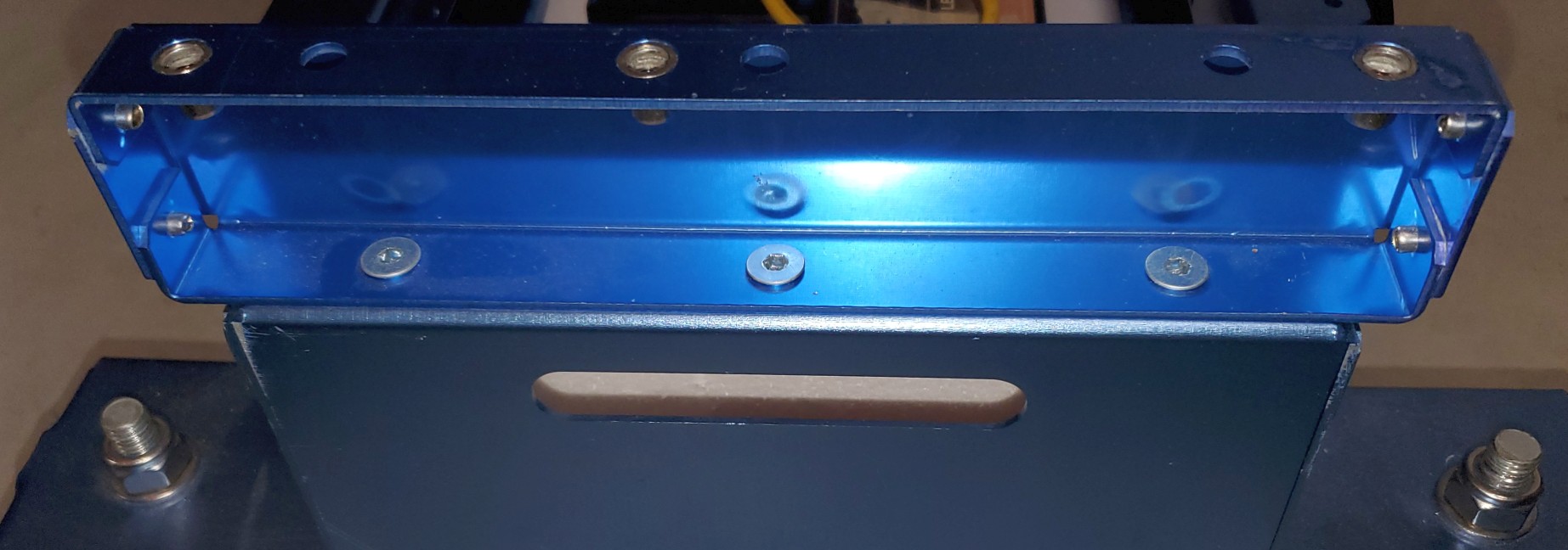 Back Bracket Viewed From Behind